Functional Testing of the Circuit Boards is a very important aspect while manufacturing and assembly. It ensures us a defect-free PCB. During manufacturing, it is important that each unit is tested for its quality and functionality.
In this article, we would like to illustrate the kind of Functional testing that is done at the different stages of manufacturing with a specific example. We look into testing that went into the manufacturing of SensePi by Appiko at LionCircuits facility. SensePi is a motion sensor that detects the movement of warm-blooded animals to trigger a camera.
The two stages of testing that we followed were the Board Level Testing (BLT) and System Level Testing (SLT).
- The primary aim of the BLT is to check that all the components are soldered properly on the PCB(s). Bare PCB itself is tested using a robotic Flying Probe Tester (FPT) at LionCircuits facility at the end of fabrication.
- The aim of the SLT is to check that all the individual components in the fully assembled product are interfaced properly.
As mentioned earlier, the aim of BLT is to make sure that each and every component and connections are soldered correctly.
- There are cases where some particular pins aren’t soldered or have dry joints.
- In other cases, there could be unintended shorts between points on the board.
That’s why it is important to understand that BLT is not to test the system performance of the device. Keeping this in mind helps in the design of the BLT. An additional aim of BLT is to permanently store information about that particular device such as any calibration data and unique device IDs. The obvious necessity of BLT is that it should be comprehensive in testing each and every section of the circuitry. Another criterion used in designing the BLT is to make it simpler for the operators to use it in the factory. So at the end of it, it should essentially say if the test has passed or failed with the additional details of the test logged for future reference.
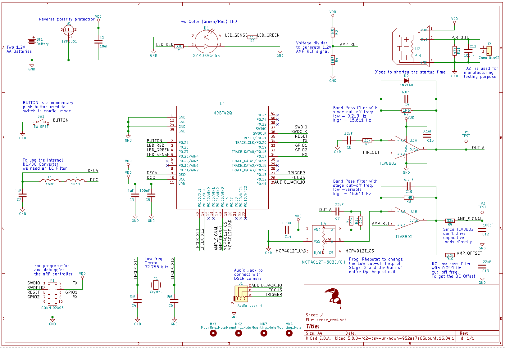
Above is the schematic of SensePi, whose assembled PCBs are the Device Under Test (DUT). You can find the KiCad project of this board here. There are various sections of this circuit and most of them are tested in BLT and the rest in SLT.
.png)
The following are tested in BLT
- Battery connector and reverse voltage protection P-channel MOSFET.
- A dual color (Red-Green) LED
- The nRF52810 based module with external inductors and 32.768 kHz crystal.
- A voltage divider for getting VDD/2 reference
- Two-stage band-pass amplifier
- A digital rheostat to change the level of amplification
- A low pass filter with 0.21 Hz cut-off to get the DC-offset of the amplifier output signal
The following are tested in SLT
- A Passive Infrared (PIR) sensor
- A connector to a button
- A connector to an audio jack
BLT Setup
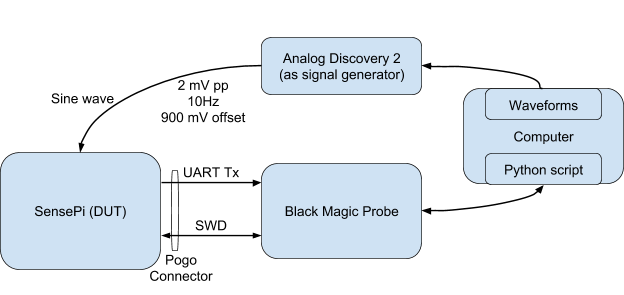
Since the SoC used in SensePi is nRF5x based we use a Black Magic Probe to program firmware on to it. We use a custom developed pogo-connector to do this. The same connector is also used to get the log of BLT over UART using the same Black Magic Probe. The connector goes on to P1 connector in the schematic.
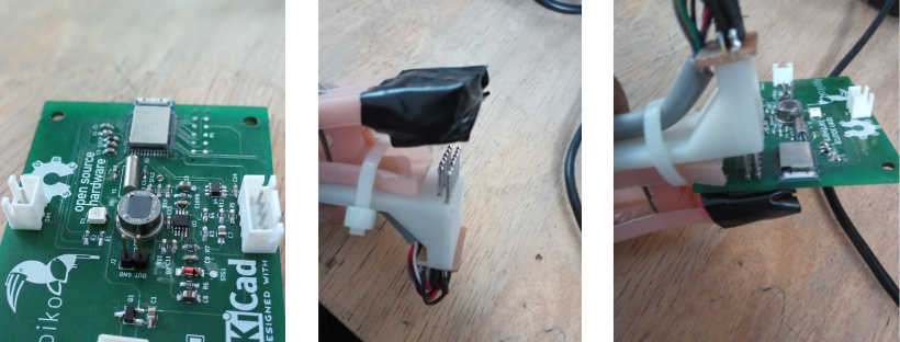
As we needed a known input source for testing the two-stage amplifier and digital rheostat portion of the circuit (right side of the schematic), we soldered the PIR sensor after BLT and tested it in SLT. In BLT, the PIR sensor’s output was replaced by the output from a signal generator. We used Analog Discovery 2’s signal generator set to a sine wave of 2 mV peak to peak at 900 mV offset with a frequency of 10 Hz.
The block diagram of the BLT test jig is as follows:
Lets take a deep dive on BLT
BLT is started by powering on the DUT board with a battery pack of 2 AA batteries in series. Then the pogo connector from the Black Magic Probe is connected to the DUT. Following this, the firmware for the BLT routine is flashed onto the DUT. If the firmware is successfully programmed it means that the battery connector, the reverse voltage protection MOSFET and the main connections of the nRF52810 module are fine. If this fails, the operator checks if the Pogo connector’s contacts are properly made before sending the board for debugging.
The BLT firmware is designed to send a log of information of the different test routines that it performs over UART back to the computer. This allows the python script running on the computer to know if and where an error has occurred during BLT. Also, the sine wave from the signal generator is connected to the point where the PIR sensor’s signal is present as the input to the amplifier circuit. Note that the PIR is not assembled during the BLT so as to get this know input signal.
After Boot
The BLT firmware makes the dual color Red-Green LED each blink for briefly. This is to be noticed by the operator and is the check for this LED’s assembly. Next, the DC-DC buck regulator of the SoC is turned on to check if the two inductors needed externally are assembled properly. So if the log sent from the BLT firmware stops before the DC-DC test, this means these inductors are missing.
Let the crystal test begin
The next test routine run is to test the 32768 kHz crystal present. For this, we enable the low-frequency crystal and see how many ticks of the high-frequency 16 MHz crystal is present in 32768 ticks of the low-frequency crystal. The high-frequency crystal is already present in the nRF52810 module, thus is assumed to be working well. This comparison of the ticks of the two crystals is compared to 1% accuracy to pass the test.
Filtering
The next test is to check if the ultra low pass RC filter with 0.21 Hz cut-off is working. This filter essentially gives a DC output at a VDD/2 reference voltage. This test validates this RC filter and the VDD/2 reference voltage from a voltage divider. This test is performed by averaging the repeated value from the Analog to Digital Conversion (ADC) of this signal for a second and averaging the value. This value is checked to see if it is within 5% accuracy with respect to a predetermined value.
The next test routine is to check if the dual stage band-pass amplifier is passing the input signal correctly. For this, we check if the frequency of the signal at the end of the two-stage amplifier is as expected. This is done by waiting for the first zero crossing of the signal and counting the number of zero crossings in a second. This will give the frequency of the signal as an integer and this is checked with the expected value.
The final stage of BLT is to test if the digital rheostat used to change the amplification of the band-pass filter with software is assembled properly. This is done by setting the rheostat to two different values and computing the ratio of the Root Mean Square (RMS) of the amplifier’s output for these two rheostat values. If this ratio is within the expected range of values, we know that the rheostat is assembled and working as expected.
Finally
If all the tests are passed, the actual firmware that runs on the product intended for the customers is flashed by the python script. In the case of SensePi there was no calibration data to be written onto the device, but that can also be done in the BLT if necessary. After this, the python script generates and writes the unique ID of the board constructed from the various information in the SoC’s non-volatile memory. The unique ID is constructed from the following elements:
- Product code
- Hardware revision number
- Factory code
- Date of manufacturing
- Incremental number of the device manufactured on that day
This way the BLT has automated the catching of faulty boards in the manufacturing of SensePi and has automated the process of storing the unique ID on the board in the manufacturing stage. We shall describe SLT in an article soon. Please do leave a comment if you think any aspect of this testing can be done better or differently.
Get Functional Testing done for FREE with Production runs
About the Author:
Prithvi Raj Narendra
Prithvi founded Appiko in Oct 2017 after realizing the lack of sustained seepage of cutting-edge technology into wildlife conservation. Before this, he was an early team member working on embedded components of a crowd-funded consumer electronic device and was part of its entire product life cycle, right from prototyping to production of 1000+ units which were delivered on time. He also led the “Embedded for Her” program, 10-week course work and project-based program to improve the gender diversity in the domain of embedded systems.